Project saviour details
To be honest with you, the planning and installation of LV switchgear is a damn complicated job. But you knew that :) There are dozen of detail where you can stumble, if not planned carefully as they should be. The later installation phase (and not to speak about commissioning phase) largely depends on the in-detail planned first phase, which usually includes the organization of transportation, design of switchgear room and clearances, various civil works, safety against arcing faults, and so on.
To be honest with you, the planning and installation of LV switchgear is a damn complicated job. But you knew that :) There are dozen of detail where you can stumble, if not planned carefully as they should be. The later installation phase (and not to speak about commissioning phase) largely depends on the in-detail planned first phase, which usually includes the organization of transportation, design of switchgear room and clearances, various civil works, safety against arcing faults, and so on.
1. Installation (clearances and corridor widths)
The minimum clearances between switchgear and obstacles specified by the manufacturer must be taken into account when installing low-voltage switchgear (Figure 1). The minimum dimensions for operating and servicing corridors in accordance with IEC 60364-7-729 must be taken into account when planning the space requirements (Figure 1, Figure 3).
Where :
- Minimum height of passage under covers or enclosures.
- Attention: Above the panels, some space specified by the manufacturer MUST be free from obstacles to allow the pressure relief vents to open in the event of an arcing fault.
Where :
- With switchgear fronts facing each other, the space requirements only account for obstruction by open doors from one side (i.e. doors that don't close in escape direction).
- Take door widths into account, i.e. door can be opened at 90° minimum.
2. Important planing considerations
- Maximum permissible panel equipment (for example, number of LV HRC in-line switch-disconnectors taking into account the disconnector size and load; the manufacturer specifications must be observed!)
- Minimum panel width taking into account the component density, cable connection cross sections and number of cables (possibly a wider terminal compartment needs to be selected or an additional panel be planned)
- The reduction factors of the devices according to the manufacturer specifications must be observed! Here, the mounting location, ambient temperature, and rated current play an important part
"This is particularly important for currents greater than 2,000 A"
- The dimensioning of compensation system largely depends on the installation site (office, production, etc.) and network conditions (harmonic content, distribution system operator specifications, audio frequency, etc.). As a rough estimate, approximately 30% (in the industry) of the transformer power can be expected if there are no concrete planning specifications.
Info!
In the case of increased use of switched-mode power supply units as, for example, for information and communication equipment in offices, the power factor might even become capacitive. It has to be noted here that these power supply units often cause system perturbations in the form of harmonics, which can be reduced by means of passive or active filters (see this technical article)
- The decision between central or distributed compensation (see chapter 5) depends on the network topology (centre of the reactive current originators).
In the case of a distributed arrangement of the compensation systems, appropriate outgoing feeders (low voltage HRC in-line switch-disconnectors, circuit-breakers, etc.) are to be provided in the low-voltage main distribution system.
- Generator-fed networks must not be compensated if a regulated compensation could lead to problems in the generator control (deactivate compensation upon switching to generator mode or use fixed compensation matched to the generator is possible).
- Choking of a compensation system depends on the requirements of the network, the customer, and also the distribution system operator.
3. Transportation switchgear units
Depending on the access routes available in the building, one or more cubicles (or columns) can be combined into transportation units. The maximum length of a transporation unit should not exceed 2,400 mm. The panel weights are to be used for the transportation and dimensioning of building structures such as cable basements and false floors.
Attention! If a lift truck is used to insert circuit-breakers or withdrawable units, the minimum corridor widths must be adapted to the lift truck!
Info!
There are a number of methods that can be used in handling the switchgear which, when properly employed, will not damage the switchgear cubicles. The handling method used will be determined by conditions and available equipment at the installation site.
Lifting with a crane is the preferred method of handling (see Figure 4), however, overhead obstructions or low ceilings often dictate the method to be used.
Moving switchgear in an obstructed area where a crane cannot be employed can be accomplished by the use of rollers (for indoor enclosure only).
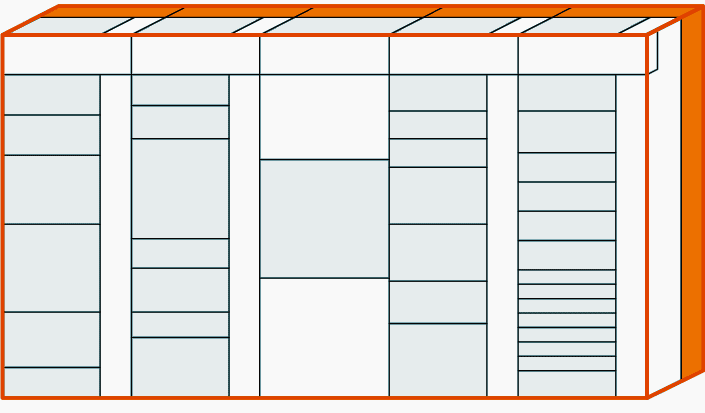
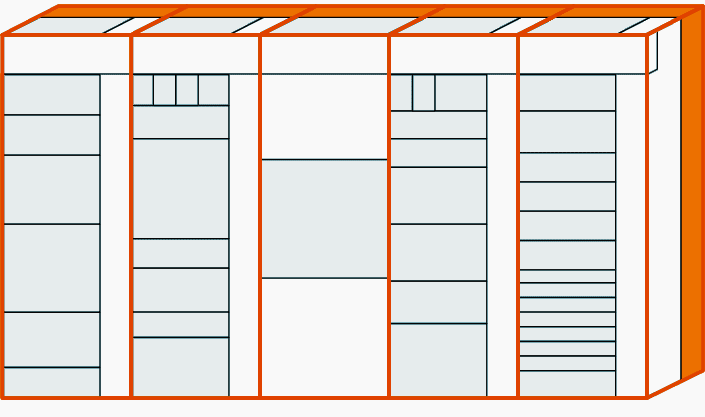
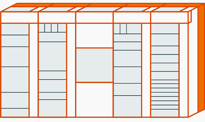
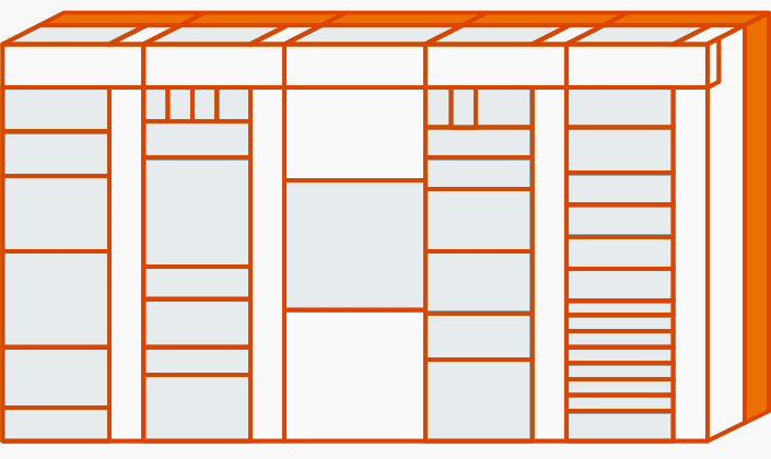
4. Double-front installations
In a double-front installation, the cubicles are positioned in a row next to and behind one another. The main feature of a double-front installation is its extremely economic design, since the branch circuits on both operating cubicles are supplied by one main busbar system only.
The double-front unitstructure is required for the assignment of certain modules.
A double-front unit in Figure 5 consists of a minimum of two and a maximum of four cubicles. The width of the double-front unit is determined by the widest panel (1) within the double-front unit. This cubicle can be placed on the front or rear side of the double-front unit. Up to three more cubicles (2), (3), (4) can be placed on the opposite side. The sum of the cubicle widths (2) to (4) must be equal to the width of the widest cubicle (1).
The panel combination within the double-front unit is possible for all technical installations with some exceptions explained below.
Exceptions!
The following cubicles determine the width of the double-front unit and may only be combined with an empty panel:
5. Environmental conditions for switchgear
The climate and other external conditions (natural foreign substances, chemically active pollutants, small animals) may affect the switchgear to a varying extent. Their effect depends on the heating and air-conditioning systems of the switchgear room.
If higher pollutant concentrations are present, reducing measures are required, for example:
6. Safety against arcing faults
As for transformers and medium-voltage switchgear, an arcing fault occurring in the low-voltage switchgear can lead to dangerous interferences with serious consequences and damage neighbouring outgoing feeders, panels or even the entire installation.
Arcing faults may arise from wrong dimensioning, insulation deterioration such as pollution, but also from handling faults. High pressure and extremely high temperatures can have fatal consequences for the operator and installation, these consequences may even extend to the entire building.
The testing of low-voltage switchgear under arcing fault conditions is a special test in compliance with IEC TR 61641.
- Measures such as high-quality insulation of live parts (for example, busbars), uniform and easy handling, integrated operator fault protection, and correct switchgear dimensioning prevent arcing faults and hence personal injuries.
- They increase operator and installation safety many times over. They include arcing-fault-proof hinge and lock systems, safe handling of withdrawable units or circuit-breakers only when the door is closed, and flap traps behind front air vents, arc barriers or an arcing fault detection system in combination with a fast interruption of arcing faults.
Info!
The effectiveness of these measures is proven by numerous elaborate arcing fault tests under worst case conditions on various panel types and functional units.
The arcing fault levels (Figure 7) describe the classification according to the properties under arcing fault conditions and the limitation of the effects of an arcing fault on the installation or parts thereof.
Arcing fault level 1
High degree of personal safety without extensive limitation of the arcing fault effects within the installation.
Arcing fault level 2
High degree of personal safety with extensive limitation of the arcing fault effects to one panel or double-front unit.
Arcing fault level 3
High degree of personal safety with limitation to the main busbar compartment on a panel or double-front unit and the device or cable connection compartment.
Arcing fault level 4
High degree of personal safety with limitation of the arcing fault effects to the place of origin.
6.1 Reducing the occurrence probability of an arcing fault
In the intensive discussion about arcing fault detection or interruption, technically elaborate and expensive solutions are readily propagated. Some manufacturers like Siemens, however, has for a long time preferred the prevention of arcing faults by means of complete insulation of all conductive parts inside the installation (busbars, connections, transfers, etc.).
Such passive precautions that no arc is generated that would have to be detected and quenched. See Figure 11.
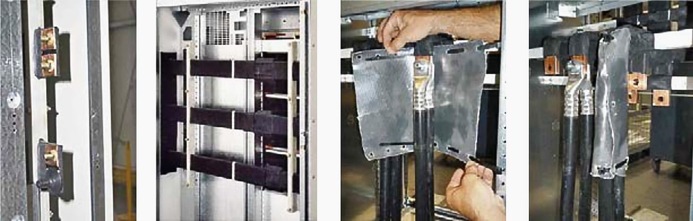
Active systems for the detection and interruption of an accidental arc as a consequence of a fault need maintenance and do not provide any advantages with regard to the installation availability. The impacts of an arcing fault (pollution, metal splashes, etc.) might be minor, but they usually have to be cleared nevertheless.
Moreover, the interruption device of the active system has to be replaced. This work can be laborious and time-consuming.
Info!
In 80 % of the cases, switchgear is installed at the wall. With a corresponding form of internal separation, the busbars are compartmentalized separately, which boosts the downtime and the effort for simple cleaning or for replacement (dismounting of the affected panel, possibly dismounting of the installation, to get to the main busbars).
Monitoring of the outgoing feeder areas of the switchgear is not recommended for active systems for reasons of reliability of supply, as arcing faults in these areas should be interrupted by the upstream protective device. Otherwise, such a fault would lead to a complete shutdown of the installation.
For feed-in monitoring (terminal compartment), the system must act on the upstream protective device. Thus, the advantage of a fast interruption by the active system is lost in the case of such a fault.
7. Other important things you should be aware
The following aspects are particularly important for the configuration of low voltage switchgear:
7.1 Environmental and installation conditions, mechanical stress
- Maximum permissible outer dimensions of the switchgear
- Maximum permissible dimensions and weight of the switchgear for transport and erection at the site of installation
7.2 Type of installation, accessibility
To ensure that the most economical design can always be selected, the main features of low voltage switchgear should be weighed against each other and a decision be made before defining the structural measures.
Such features are:
7.3 Selection of the electrical equipment
The following has to be considered for the equipment to be installed in switchgear assemblies:
7.4 Protective measures
7.5 Space requirements for built-in units, busbars and terminals
When configuring built-in components in encapsulated switchgear and distribution switchboards, sufficient space must be provided beyond the pure space requirements of the units for:
Info!
In the project documentation as well as in the completed switchgear assembly, the devices belonging together have to be designated clearly. This also applies to the assignment of fuses to circuits.
Meters and measuring instruments should be located at eye level. All devices that are to be operated manually should be within reach (approximately at a height between 0.6 and 1.8 m). Restrictions resulting from the use of a device in an encapsulation might have to be observed, for example, with regard to the rated current and the switching capacity.